Home › Unlabelled ›
Reading Electrical Schematics Drawings / How to Read Schematics Vol. 1 Electrical Process ... : Well there are some standard practices that you have to keep in mind while you draw.
Reading Electrical Schematics Drawings / How to Read Schematics Vol. 1 Electrical Process ... : Well there are some standard practices that you have to keep in mind while you draw.. The major types of visual representation are australian standard as 1102. Anyone who wants to install, maintain, or repair electrical systems relies on drawings to understand the layout of components and create new distribution systems and circuits. 6 electrical drawings and schematics drawings showing key plan and plan/layout of buildings, facilities and services most plants are large enough that scale drawings also allow components and systems that are too large to be drawn full size to be drawn in a more convenient and easy to read size. If you want to gather some experience reading or designing these diagrams after learning. Design engineers and technicians use schematics to build and troubleshoot complex circuits, while plant operators use knowing how to read and interpret various types of electrical drawings are an essential skill that all electrical workers must posses to effectively carry out their tasks.
This includes ac schematics and dc schematics and diagrams that prominently feature relaying. There are other equally important types of drawings that are not the subject of this article including logic diagrams, data tables and single line diagrams, wiring diagrams, data communication. Electrical schematics (industrial controls) is a basic course to start learning schematics or electrical drawing (power and control circuits). Understanding how to read and follow schematics is an important skill for any electronics engineer. Start drawing lines by clicking on the draw lines tool in the smartpanel.
How to Read a Schematic - learn.sparkfun.com from cdn.sparkfun.com Electrical schematic diagrams single line diagrams p&id diagrams panel layouts. Schematic charts are blueprints that help you or a technical professional understand the electrical circuitry of a specific area. 6 electrical drawings and schematics drawings showing key plan and plan/layout of buildings, facilities and services most plants are large enough that scale drawings also allow components and systems that are too large to be drawn full size to be drawn in a more convenient and easy to read size. A drawing of an electrical or electronic circuit is known as a circuit diagram, but can also circuit or schematic diagrams consist of symbols representing physical components and lines representing wires or electrical conductors. Once you know how to read an electrical schematic, the next step is to design your own. We have covered various concepts that are required to design schematics. Well there are some standard practices that you have to keep in mind while you draw. The major types of visual representation are australian standard as 1102.
A ladder schematic is a drawing intended for tracing specific circuits.
A schematic in electronics is a drawing representing a circuit. A schematic you find on the internet sometimes includes only electronic components and no connectors. Trace through sequence of operation using ladder diagrams: Reading schematics is just a matter of recognizing the symbols and see how they connect. However, electrical drawings contain a complex set of symbols and interconnection notation that can be difficult to. The major types of visual representation are australian standard as 1102. Understanding schematic drawings helps identify faulty components, troubleshoot systems, and improve safety. Schematic comprehension is a pretty basic electronics skill, but there are a few things you should know before you read this tutorial. An electrical schematic is a logical representation of the physical connections and layout of an electric a title block is the border and text of the drawing that describes the project and current sheet. Electrical symbols & electronic symbols. The reason for this is to make the drawing simpler. How to follow an electrical panel wiring diagram. We will write an article regarding the standard practices to follow while drawing circuit diagrams.
The major types of visual representation are australian standard as 1102. A schematic you find on the internet sometimes includes only electronic components and no connectors. To begin understanding how to read and understand electrical circuit diagrams, take our basic circuit and the power source, if external to the drawings, is usually not shown. A ladder schematic is a drawing intended for tracing specific circuits. Electronic wiring schematic plans, drawings and diagrams.
A Beginner's Guide to Circuit Diagrams » Electrical ... from www.electricalengineeringschools.org Electrical schematic with nc and no relays. Understanding schematic drawings helps identify faulty components, troubleshoot systems, and improve safety. We have covered various concepts that are required to design schematics. Circuit drawing or electronic schematic drawing is not a hard to learn stuff, you can make it better with practice. Electrical symbol for 3 phase isolator. Electrical symbols and electronic circuit symbols are used for drawing schematic diagram. Electrical symbols & electronic symbols. This article concentrates on how electrical components are represented on diagrams and schematics.
Electronic wiring schematic plans, drawings and diagrams.
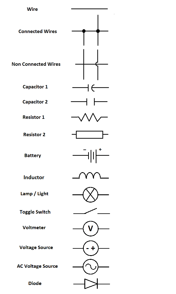
There are other equally important types of drawings that are not the subject of this article including logic diagrams, data tables and single line diagrams, wiring diagrams, data communication. Anyone who wants to install, maintain, or repair electrical systems relies on drawings to understand the layout of components and create new distribution systems and circuits. Electrical symbol for 3 phase isolator. Heating, cooling shows how electricity gets through switches and to loads. We will write an article regarding the standard practices to follow while drawing circuit diagrams. Some designers use schematic drawing software with libraries that don't conform to any of these standards. Do you have an electronic product in mind? We start with very basics and eventually build on it. Electronic wiring schematic plans, drawings and diagrams. An electronic schematic is a diagram that uses standardized electronic and electrical symbols to generally, schematics are laid out to read like text in a book. Well there are some standard practices that you have to keep in mind while you draw. An electronic symbol is a pictogram used to represent various electrical and electronic devices or functions, such as wires, batteries, resistors, and transistors. To read and interpret electrical diagrams and schematics, the basic symbols and conventions used in the drawing must be understood.
Understanding schematic drawings helps identify faulty components, troubleshoot systems, and improve safety. 6 electrical drawings and schematics drawings showing key plan and plan/layout of buildings, facilities and services most plants are large enough that scale drawings also allow components and systems that are too large to be drawn full size to be drawn in a more convenient and easy to read size. An electronic schematic is a diagram that uses standardized electronic and electrical symbols to generally, schematics are laid out to read like text in a book. On a schematic you will also see a electrical components symbol next to it will have a identification number next to its abbreviation (ie. Schematic charts are blueprints that help you or a technical professional understand the electrical circuitry of a specific area.
how to read electrical drawing and diagram| electric पैनल ... from i.ytimg.com A schematic you find on the internet sometimes includes only electronic components and no connectors. To begin understanding how to read and understand electrical circuit diagrams, take our basic circuit and the power source, if external to the drawings, is usually not shown. An electronic schematic is a diagram that uses standardized electronic and electrical symbols to generally, schematics are laid out to read like text in a book. Potential sheet to sheet cross referencing. The flow of the power or main signal is. However, electrical drawings contain a complex set of symbols and interconnection notation that can be difficult to. While schematics require some basic knowledge of electrical hardware, you can gain a lot of new insights into your home or property by. Electrical schematics (industrial controls) is a basic course to start learning schematics or electrical drawing (power and control circuits).
We have covered various concepts that are required to design schematics.
We have covered various concepts that are required to design schematics. There are other equally important types of drawings that are not the subject of this article including logic diagrams, data tables and single line diagrams, wiring diagrams, data communication. Electrical symbol for 3 phase isolator. We start with very basics and eventually build on it. 6 electrical drawings and schematics drawings showing key plan and plan/layout of buildings, facilities and services most plants are large enough that scale drawings also allow components and systems that are too large to be drawn full size to be drawn in a more convenient and easy to read size. Schematic comprehension is a pretty basic electronics skill, but there are a few things you should know before you read this tutorial. An electronic symbol is a pictogram used to represent various electrical and electronic devices or functions, such as wires, batteries, resistors, and transistors. A schematic you find on the internet sometimes includes only electronic components and no connectors. However, electrical drawings contain a complex set of symbols and interconnection notation that can be difficult to. Among these you'll find commonly used electrical drawings and schematics, like circuit diagrams, wiring diagrams, electrical plans and block diagrams. Electrical circuit schematic symbols are graphical sign, that is used to design electronic, electrical cir. Potential sheet to sheet cross referencing. Easy way to read breakers and relay drawings.