Intermatic Timer Wiring Diagram - Intermatic ET1105C 24 Hour Electronic Time Switch, Wall ... : User manuals, intermatic timer operating guides and service manuals.. The 555 timer, designed by hans camenzind in 1971. We show where to connect the neutral wire. You can watch the following video or read the written tutorial below. Click on an alphabet below to see the full list of models starting with that letter Notify me when this product is in stock.
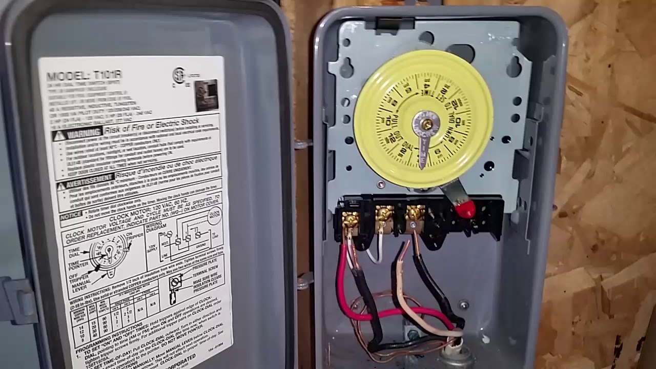
Intermatic ei500 series installation instructions warning: How to wire intermatic t104 and t103 and t101 timers intended for intermatic timer wiring diagram, image size 587 x 450 px, and to view image details please click the image. We show how to test the timer. Check out the diagram below, or see the wiring diagram which comes with a new timer, or is printed on the door of the timer box. Get free shipping on qualified intermatic timers or buy online pick up in store today in the electrical department.
Get Intermatic Timer T104 Wiring Diagram Sample from worldvisionsummerfest.com It reveals the components of the circuit as streamlined forms, and also the power and also signal connections in between the tools. Many pool pump motors and water heaters use intermatic timers to regulate their run times. How to wire intermatic t104 and t103 and t101 timers intended for intermatic timer wiring diagram, image size 587 x 450 px, and to view image details please click the image. Intermatic 240v timer wiring diagram | free wiring diagram name: Remove wall plate and disconnect existing wall switch. Intermatic timer wiring diagram t101. Check out the diagram below, or see the wiring diagram which comes with a new timer, or is printed on the door of the timer box. Type of wiring diagram wiring diagram vs schematic diagram how to read a wiring diagram:
Type of wiring diagram wiring diagram vs schematic diagram how to read a wiring diagram:
This pictorial diagram shows us the. To avoid risk of fire or shock which could result in injury or death, turn of power at circuit breaker and test that power is off before wiring. It reveals the components of the circuit as streamlined forms, and also the power and also signal connections in between the tools. Used remote switches from a previous. User manuals, intermatic timer operating guides and service manuals. Get free shipping on qualified intermatic timers or buy online pick up in store today in the electrical department. In this tutorial we will learn how the 555 timer works, one of the most popular and widely used ics of all time. I'm no good at wiring diagrams. Click on an alphabet below to see the full list of models starting with that letter View our diagram for intermatic time clock parts. Installing instruction for installing an intermatic t101 or t103. Larger image t104 timer and t106 timer together. Notify me when this product is in stock.
A wiring diagram is a simplified standard photographic depiction of an electric circuit. Intermatic timer t104 wiring diagram download july 12, 2019 by wholefoodsonabudget assortment of intermatic timer t104 wiring diagram. Intermatic intermatic time clock parts. News and events applications and solutions product highlights energy efficiency videos. You can watch the following video or read the written tutorial below.
How To Wire Connect Intermatic Pool Pump Timer SIMPLE ... from i.ytimg.com To wire time switch as desired, see wiring diagram above. The 555 timer, designed by hans camenzind in 1971. Check out the diagram below, or see the wiring diagram which comes with a new timer, or is printed on the door of the timer box. We show how to test the timer. I'm no good at wiring diagrams. Intermatic 240v timer wiring diagram | free wiring diagram name: The t106 timer is either high or low speed, but never. Intermatic time clock motors can be replaced, but unless the time clock was fairly new, i'd probably just replace the entire intermatic mechanism.
Intermatic time clock motors can be replaced, but unless the time clock was fairly new, i'd probably just replace the entire intermatic mechanism.
Manualslib has more than 205 intermatic timer manuals. Intermatic ei500 series installation instructions warning: The 555 timer, designed by hans camenzind in 1971. A wiring diagram is a streamlined traditional photographic depiction of an electrical circuit. Notify me when this product is in stock. You can watch the following video or read the written tutorial below. We show where to connect the neutral wire. How to wire connect intermatic pool pump timer simple short video. View our diagram for intermatic time clock parts. Check out the diagram below, or see the wiring diagram which comes with a new timer, or is printed on the door of the timer box. The t106 timer is either high or low speed, but never. Icons that represent the components in the circuit, as well as lines that represent the connections between. Switch timer does not catch up automatically to the programmed load state.
It reveals the components of the circuit as streamlined forms, and also the power and also signal connections in between the tools. Resources how to wire intermatic control center breaker busbar control center is a subpanel: To avoid risk of fire or shock which could result in injury or death, turn of power at circuit breaker and test that power is off before wiring. Intermatic timer t104 wiring diagram download july 12, 2019 by wholefoodsonabudget assortment of intermatic timer t104 wiring diagram. You can watch the following video or read the written tutorial below.
30 Intermatic Pool Timer Wiring Diagram - Wiring Diagram List from ww2.justanswer.com We show where to connect the neutral wire. An intermatic timer is a timer that you can install in your home and connect to anything with a power source, such as lights, to program them to turn on and off at certain times of day. News and events applications and solutions product highlights energy efficiency videos. It reveals the components of the circuit as streamlined forms, and also the power and also signal connections in between the tools. To wire time switch as desired, see wiring diagram above. A wiring diagram is a simplified standard photographic depiction of an electric circuit. Timers timers timers bathroom lighting hallway lighting holiday lights lamps ent ry light ing display lighting saunas small appliances security lighting whirlpools www.intermatic.com 47 timers set it and forget it a. Check out the diagram below, or see the wiring diagram which comes with a new timer, or is printed on the door of the timer box.
Timers timers timers bathroom lighting hallway lighting holiday lights lamps ent ry light ing display lighting saunas small appliances security lighting whirlpools www.intermatic.com 47 timers set it and forget it a.
I'm no good at wiring diagrams. Manualslib has more than 205 intermatic timer manuals. Ntroduction thank you for purchasing intermatic ej500 indoor wall switch timer with astronomic feature. The wiring diagram is a little difficult to comprehend but once you understand what it's showing you, it's simple and straightforward to hook up. Intermatic incorporated manufactures timer switches designed for indoor and outdoor use. Click on an alphabet below to see the full list of models starting with that letter View our diagram for intermatic time clock parts. I need a wiring diagram for an intermatic timer model. Installing instruction for installing an intermatic t101 or t103. Used remote switches from a previous. Larger image t104 timer and t106 timer together. Intermatic intermatic time clock parts. How to wire intermatic t104 and t103 and t101 timers intended for intermatic timer wiring diagram, image size 587 x 450 px, and to view image details please click the image.