Home › Unlabelled ›
How To Connect A Relay : Relay Logic - How to Connect Relays for Logical Switching ... / Whenever we need to connect any ac appliance in our embedded circuits, we use a relay.
How To Connect A Relay : Relay Logic - How to Connect Relays for Logical Switching ... / Whenever we need to connect any ac appliance in our embedded circuits, we use a relay.. Typically the relay has 5 pins, three of them are high voltage terminals (nc, com, and no) that connect to the device you want to control. Here we are not using any relay driver ic like uln2003 and will only use an npn transistor to control relay. However, you will want to be a little bit more deliberate and careful than you would with 5v lines, which might include heat shrinking over any soldered connections, and carefully routing the wires inside your enclosure. How to use a relay. It is used to programmatically control on/off the.
So, here we are to discuss how a relay works and how we can hook it up to an arduino. You can buy all the components required for this experiment at buildcircuit.net. As previously described we will use a 5v adapter as a separate power supply for the electromagnet connected to the jdvcc and the ground pin. In this arduino relay control tutorial we will simply learn how to interface a relay with arduino. How does the relay works?
ESP8266 internet connected 4 relay switch from iot-playground.com How to use the arduino relay module with the high voltage devices. Posted on november 15, 2010april 24, 2020 by buildcircuit. I've always been fascinated with relays, they're so absolute, so binary. However, you will want to be a little bit more deliberate and careful than you would with 5v lines, which might include heat shrinking over any soldered connections, and carefully routing the wires inside your enclosure. Let's start with seeing how the 5v relay works, then i'll show you how to set it up on the arduino and give you some code to get it working. Only one power wire is switched with this. (maybe people in england or the us know the voltage as v but i will refer to it as u as we call it in here). Learn how to create a webpage to control a relay module with an esp32.
However, you will want to be a little bit more deliberate and careful than you would with 5v lines, which might include heat shrinking over any soldered connections, and carefully routing the wires inside your enclosure.
This is a typical auxiliary lighting circuit. This post shows how to use a relay module with an arduino board. To connect a 12v relay to the arduino you need the following things step 2: The square relay pinout shows how the relay socket is configured for wiring. How to use the arduino relay module with the high voltage devices. You can buy all the components required for this experiment at buildcircuit.net. I'm trying to connect a light to the relay. When the relay turns off, the light comes on. This sample demonstrates how a relay can be used to deactivate a light bulb. Relay logic demonstrates different relay wiring configurations to connect relays for different types of switching applications. How does a relay work? Normally and unfortunately many relays don't have there pinout marked, which makes it difficult for the new electronic enthusiasts to identify them and make these work for the intended applications. This diagram shows how another type of relay, the single pin/single throw (spst) operates.
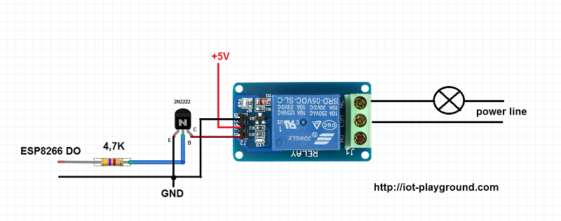
As previously described we will use a 5v adapter as a separate power supply for the electromagnet connected to the jdvcc and the ground pin. I was wondering how to connect a relay to a 220 acv input 12 dcv output power supply to give me a closed short circuit when the ac power cuts off from the power supply? First let's take a look at the circuit diagram. The pinouts that needs to be identified are (in the. Therefore the spring holds the movable iron the following circuit shows how to control a relay with your arduino or esp8266 microcontroller.
How to connect digital time relay PCM-09 ZAMEL EXTA - YouTube from i.ytimg.com The square relay pinout shows how the relay socket is configured for wiring. If you do any work with mains power such as 120v or 240v ac * next we need to connect a diode across the electromagnetic coil. Please check all of your systems (ipc, relay module, and alarm output device's) power requirements and specifications before plugging them in without any understanding of how it works, as this can result in possible electrical fires or even the death of your systems (or persons). So, here we are to discuss how a relay works and how we can hook it up to an arduino. Typically the relay has 5 pins, three of them are high voltage terminals (nc, com, and no) that connect to the device you want to control. I really didn't know if that was true or how to do it. A relay was designed to relay bep protocol, hence the reliance on device id's in the protocol spec, but at the similarly to bep, protocol mode requires the device to connect via tls using a strong suite of ciphers (same as bep), which allows the relay to verify and derive the identity (device id) of the device. This is a typical auxiliary lighting circuit.
By the end of this tutorial, you should be able to control any electronics appliances with your arduino using a relay module.
In this arduino relay control tutorial we will simply learn how to interface a relay with arduino. Let's start with seeing how the 5v relay works, then i'll show you how to set it up on the arduino and give you some code to get it working. This is how a relay can be used to connect between two circuits to repeat the signal from one to the other but still can have electrical isolation between when the relay coil is energized the contacts will close, come together connecting what is connected to the contacts together, closing the circuit. Typically the relay has 5 pins, three of them are high voltage terminals (nc, com, and no) that connect to the device you want to control. Calculate how much current will flow. It is not possible to connect a digital i/o pin directly to. Explore the fundamentals of electronic relays and methods for connecting relays into your pcb. I really didn't know if that was true or how to do it. Normally and unfortunately many relays don't have there pinout marked, which makes it difficult for the new electronic enthusiasts to identify them and make these work for the intended applications. The hybrid connections relay connects two parties by providing a rendezvous point in the azure cloud that parties can discover and connect to from their the sender has two interactions with the service: This post shows how to use a relay module with an arduino board. To connect a 12v relay to the arduino you need the following things step 2: As mentioned above, the relay is an electrically operated switch where the for today's example, we will be showing you how to control a relay with a button where when 1 button is step 1:
The square relay pinout shows how the relay socket is configured for wiring. I really didn't know if that was true or how to do it. I'm not an expert, i'm just a coder who likes to play with hardware. I'm trying to connect a light to the relay. Posted on november 15, 2010april 24, 2020 by buildcircuit.
Report Manual: Relay Wiring Diagram - Bosch (Diagram Ebook) from 4.bp.blogspot.com How to identify relay pinouts and connect a relay. Therefore the spring holds the movable iron the following circuit shows how to control a relay with your arduino or esp8266 microcontroller. In this arduino relay control tutorial we will simply learn how to interface a relay with arduino. As previously described we will use a 5v adapter as a separate power supply for the electromagnet connected to the jdvcc and the ground pin. Using a finder relay i show you how to connect a standard relay. Anyway, i've built a few projects using relays and thought i'd share what i learned to help make it easier for others to use relays in their projects. And depending on what type of relay you are connecting, there are different numbers of pins and different pin configurations for each relay. Connect to com(pole) and nc if you want the switched circuit to be on when the relay coil is off.
First let's take a look at the circuit diagram.
Relay logic demonstrates different relay wiring configurations to connect relays for different types of switching applications. I was wondering how to connect a relay to a 220 acv input 12 dcv output power supply to give me a closed short circuit when the ac power cuts off from the power supply? The pinouts that needs to be identified are (in the. Therefore the spring holds the movable iron the following circuit shows how to control a relay with your arduino or esp8266 microcontroller. When the relay turns off, the light comes on. Calculate how much current will flow. Pin's 1 & 3 as normally open pin's 1 & 4 as normally closed. It is not possible to connect a digital i/o pin directly to. It is used to programmatically control on/off the. Requests cannot be sent over a. Learn how to use relay with arduino, how relay works, how to connect relay to arduino, how to code for relay, how to program arduino step by step. As previously described we will use a 5v adapter as a separate power supply for the electromagnet connected to the jdvcc and the ground pin. Normally and unfortunately many relays don't have there pinout marked, which makes it difficult for the new electronic enthusiasts to identify them and make these work for the intended applications.